The effects of thermal expansion are such that from the warmest to the coldest day of the year the height of the Eiffel tower can vary by 15cm. Building systems with consideration to the effects of thermal expansion is common place in engineering applications. Well cited design techniques include expansion joints in bridges, which allow movement and pre-stressed railway tracks which limit the temperature for which expansion occurs. Accommodating for thermal expansion in a system is often key to ensuring longevity and power cable systems are no different.
For a cable system, changing temperatures typically arise from seasonal differences in ambient temperature and variances in circuit demand causing the conductor temperature of the cable to change. The latter often has the largest impact on the design temperature range which is approximately 90°C for most applications. Typically, cleated cable installations utilise two methods to accommodate for thermal expansion:
1)Rigid Installation
For rigid type cable installations the cable is laid straight and no movement of the cable is permitted. In order to achieve this the cable supports must be strong enough to resist the thermomechanical (thermal expansion and contraction) forces. Rigid systems are best suited to buried installations with the movement of the cable being restrained by well compacted back fill. For instances where a rigid style system is to be installed in air the cable is cleated at short intervals. A cleated rigid style installation is shown in Fig. 1. Proper cleating of cable firstly ensures that the thermomechanical thrust force of the cable is restrained by the cleats, preventing cable movement, and secondly that the cable does not buckle under said thrust force. Cleats that offer a high axial thrust restraint, such as Ellis’ 2A clamp, are best suited to rigid type systems. 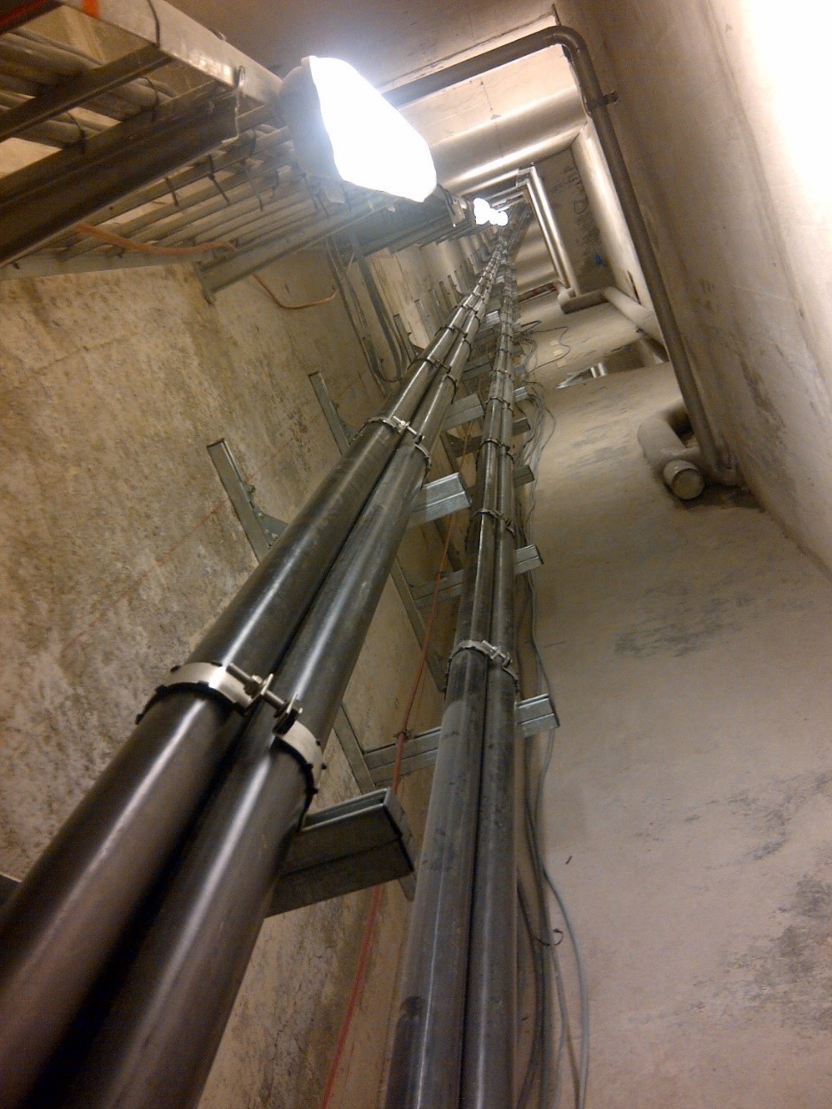 Fig. 1 – Rigid style cable installation.
2) Flexible Installation
For flexible style systems the cable is laid in a snaked formation. The cable can either be snaked ‘vertically’ whereby the cable is sagged between intermittent supports (approximately 7 – 10m intervals) as shown in Fig. 2. Alternatively a ‘horizontally’ snaked system can be utilised, for which the cable is snaked within the confines of a support structure as shown in Fig. 3. Regardless of the snake type the intention of the system is to allow the snake/sag to grow in periods of high circuit demand (high conductor temperature) and contract during low use periods and thus, impart a relatively low thrust force to the cleats and support structure. For flexible installations it is imperative that an appropriate cable snake geometry is determined based on the system requirements. Typical considerations include; metallic sheath fatigue characteristics, space limitations and cable bending stiffness.
The cleats best suited to vertically snaked systems have a large saddled base to properly support the cable across the large structure span. Ellis’ Centaur is specifically designed for vertically snaked flexible systems. Cleats for horizontal style snakes are typically less specialist. They require a robust cleat to hold the cable at inflection points and for certain applications cleats placed between inflection points that can slide along the structure as the cable moves. 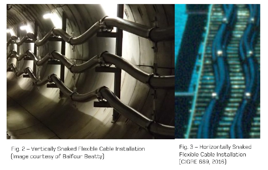 Failing to accommodate for thermal loading of cable systems can result in circuit failures. Typically these occur at vulnerable points along the cable run where uncontrolled cable movement can cause buckling of joints and damage to terminations. This article only offers a short summary of the methods used in designing for HV cable systems. CIGRE technical brochures 194 and 669 offer comprehensive coverage of the techniques used in cable system design. Ellis have excellent experience in providing products correctly suited for flexible and rigid style systems and are happy to assist with customer projects.
References:
CIGRE Technical Brochure 194 ‘Construction, Laying and Installation Techniques for Extruded and Self Contained Fluid Filled Cable Systems’ (2001).
CIGRE Technical Brochure 669 ‘Mechanical forces in large cross section cable systems’ (2016).
Harry Taylor (Mechanical Engineer) – 02/09/19
