SOLUS® CLAMP
Data sheet DS49E
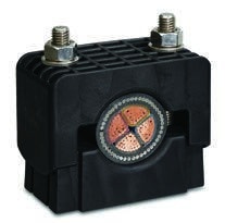
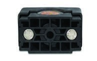
Twin fixing / single fixing
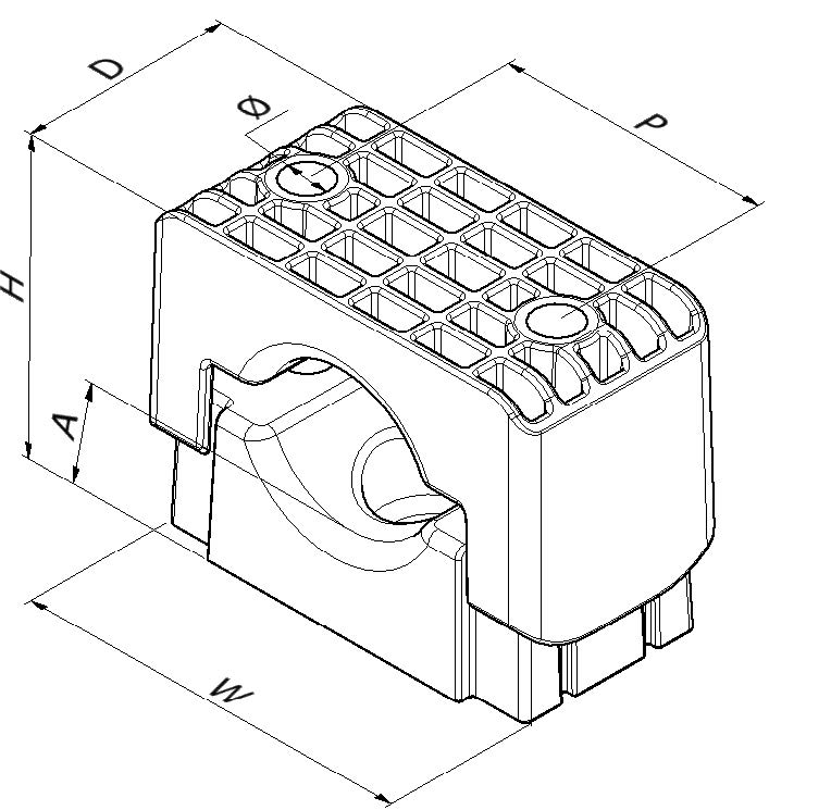
Standard duty cable clamp for single cable formation.
Stackable design allows easy future cable additions.
Cable range of Ø19mm – Ø90mm.
Available in two materials: standard material (LSF) is PFAS and halogen-free, flame retardant and suitable for outdoor applications; for higher-temperature applications, GFN has the same material properties as LSF but offers a higher operating temperature, and the material has a UL94 V-0 flammability rating.
Optional Low Smoke and Fume Zero Halogen (LSF0H), phosphorus-free polymeric liners available, for increased cable protection. The liner size is 3mm.
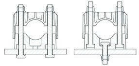
Fixing options: single- or twin-bolt fixing options; sizing shown in the table below. M12 fixings are required but not supplied as standard, but are available on request.
Designed, tested and manufactured in accordance with IEC 61914.
Note: for clamp with liner add L suffix.
E.g. SL25-38GFNL.
| Part No. | Cable Range | Cable Range with Liner | Dimensions | Axial Load (kN) | Lateral Load - Horizontal (kN) | Lateral Load - Vertical (kN) | Weight (g) | |||||||||
|---|---|---|---|---|---|---|---|---|---|---|---|---|---|---|---|---|
| Min Ø (mm) | Max Ø (mm) | Min Ø (mm) | Max Ø (mm) | W | H | D | A | P | Single Fixing | Twin Fixing | Single Fixing | Twin Fixing | Single Fixing | Twin Fixing | ||
| SL25-38GFN | 25 | 38 | 19 | 32 | 99 | 80 | 60 | 24 | 60 | 0.9 | 1.2 | 4 | 5 | 6.5 | 10 | 285 |
| SL36-52GFN | 36 | 52 | 30 | 46 | 115 | 95 | 60 | 24 | 75 | 1.2 | 1.8 | 4 | 5.5 | 6 | 10 | 356 |
| SL49-75GFN | 49 | 75 | 43 | 69 | 135 | 124 | 60 | 26 | 95 | 1.6 | 1.6 | 4 | 10 | 6.5 | 9 | 485 |
| SL66-90GFN | 66 | 90 | 60 | 84 | 158 | 142 | 70 | 26 | 120 | 1.6 | 1.6 | 6.5 | 10 | 10 | 10 | 655 |
| SL25-38LSF | 25 | 38 | 19 | 32 | 99 | 80 | 60 | 24 | 60 | 1.1 | 1.3 | 6.5 | 7 | 10 | 25 | 232 |
| SL36-52LSF | 36 | 52 | 30 | 46 | 115 | 95 | 60 | 24 | 75 | 1.1 | 1.8 | 6 | 8 | 9 | 25 | 287 |
| SL49-75LSF | 49 | 75 | 43 | 69 | 135 | 124 | 60 | 26 | 95 | 1.1 | 1.1 | 6 | 8 | 10.5 | 26 | 395 |
| SL66-90LSF | 66 | 90 | 60 | 84 | 158 | 142 | 70 | 26 | 120 | 1.1 | 1.1 | 6.5 | 8 | 10 | 25 | 548 |
SOLUS® CLAMP
Data sheet DS49E
Testing Summary
Solus Clamps have been tested in line with the International Standard “Cable Cleats for Electrical Installations” IEC 61914. Typical results are detailed below, please note that these testing values are maximums and safety factors appropriate to your application should be used:
| Test Data | ||||
|---|---|---|---|---|
| Property Classification | Clause IEC 61914 | Units / Classification | LSF | GFN |
| Cleat type | 6.1.2 | Non-metallic | - | - |
| Temp. for permanent application | 6.2 | °C | -60 to +60 | -60 to +120 |
| Impact rating | 6.3.5 | Very heavy | Pass | Pass |
| Flame propagation test | 10.0, 10.1 | Flame propagation test ≥30s | Pass | Pass |
| Axial load (kN) | 6.4.3, 9.4 | Newtons (N) | See table on opposite page | See table on opposite page |
| Lateral load rating | 6.4.2, 9.3 | Newtons (N) | See table on opposite page | See table on opposite page |
| Additional lateral load rating | 6.4.2, 9.3 | Newtons (N) | Horizontal - 2250N Vertical - 2250N | Horizontal - 2250N Vertical - 2250N |
| Resistance to electromechanical force (short circuit testing) | 6.4, 6.4.5, 9.5 | Cleats at 300mm intervals (withstanding more than one short circuit) | 157kA (Report No. PDL-22.079.02) Cable OD = Ø35mm *Phase spacing = 125mm | 164kA (Report No. PDL-22.079.01) Cable OD = Ø35mm *Phase spacing = 125mm |
| Resistance to electromechanical force (short circuit testing) | 6.4, 6.4.5, 9.5 | Cleats at 600mm intervals (withstanding more than one short circuit) | 136kA (Report No. LCOE 2025 05 35 0317-9) Cable OD = Ø37.5mm #Phase spacing = 125mm | 119kA (Report No. LCOE 2025 05 35 0317-8) Cable OD = Ø37.5mm #Phase spacing = 125mm |
Note: the with liner version has a lower rating to the standard version as follows: temperature range of -60 to +85°C; axial performance lower than standard version, contact Ellis for details.
* Results obtained using 2x M12 316L A4-70 grade stainless steel fixings. # Results obtained using 2x M10 316L A4-70 grade stainless steel fixings.
Product can be stacked flat using hex recess on base of product - refer to installation instructions.
Lateral load: vertical direction
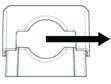
Lateral load: horizontal direction

Product can be stacked flat using hex recess on base of product - refer to intsallation instructions
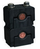
Fixing options